


Published on Apr 02, 2024
Quasi turbine is a zero vibration continuous combustion rotary engine having four faces articulated rotor with a free and accessible centre rotating without vibration nor dead time and producing a strong torque at low rpm under a variety of modes and fuels. The quasi turbine is also an optimization theory for extremely compact efficient engine concept.
It is a new engine concept from Canada offers a design similar to that of rotary engines but with the advantages of a gas turbine-all within the confines of a chamber based on the shape of a Saint Hilaire skating rink profile. Each Quasi turbine device is at the cross road of three modern engines: inspired by the turbines: it perfects the piston, and improves on the Wankel. The Quasi turbine results from a research initiated in 1993 aimed at unifying the compression and power turbine into one entity.
This invention is a new hybrid engine concept, midway between the piston and the turbine engine which requires relatively few components such as stator with covers, rotating blades, rocking carriages, wheels, and joints. Quasiturbine is also an environmental friendly engine, which provides an engine concept free from atmospheric gas pollution, noise pollution, thermal pollution etc. In this engine efficiency stays constant and optimum no matter the power of the unit.
Inventors: - Francoise, Gilles, Roxan
Object of this invention is to provide new engine concept unifying the compressor and power turbine into one entity that is a conventional gas turbine engine. Another object of this invention is to provide a low noise, perfectly balanced, zero vibration, low r.p.m engine, giving less time to compression and expansion stroke and allowing more time and volume to the intake combustion stroke.
A further object of this invention is to provide a fast accelerating, zero dead time and to provide an engine almost universal to energy sources, which can run efficiently on pneumatic, steam, hydraulic, liquid and gas fuel internal combustion.
Another object is to provide an engine, which has a short pressure peak, cold intake area characteristics, so that it is suitable for photo detonation mode pure hydrogen fuel combustion.
Another object is to provide a high weight and volume density engine, without need of any valve, check valve or obstruction and within neither a crankshaft nor a flywheel.
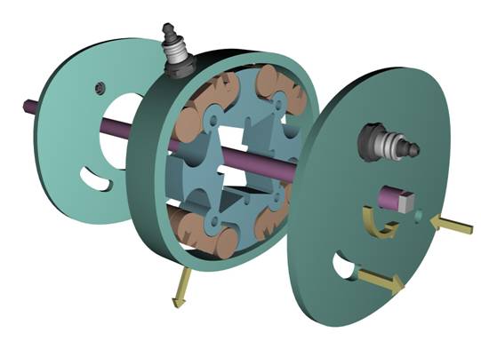
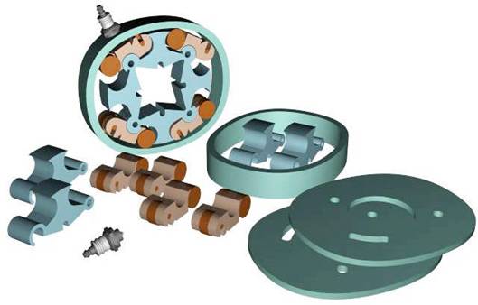
The invention is an assembly of four carriages supporting the pivots of a four element, variable shape rotor, which is confined within a chamber (internal housing counter wall-stator) based on the shape of a Saint Hilaire skating rink profile. This profile offers the rotary components of the engine a bigger, more uniform radial path, enabling maximum torque to be reached more efficiently than a normal combustion.
Two lateral plane covers close the engine end. The rotor is composed of four pivoting blades playing a similar role as the piston or turbine blades. Each pivots sit into one of the four rocking carriages. Each carriage is free to rotate around the same pivot in such a way as to be continuously and precisely in contact with housing counter.
A central shaft is not needed for the engine to operate. It can be driven through a set of coupling arms attached to the blades by means of traction slots and through a set of arm braces, the ends of which are linked to central shaft. The central shaft unit can be easily removed through the back cover central hold with out dismantling the engine
The invention is an assembly of four carriages supporting the pivots of a four element, variable shape rotor, which is confined within a chamber (internal housing counter wall-stator) based on the shape of a Saint Hilaire skating rink profile. This profile offers the rotary components of the engine a bigger, more uniform radial path, enabling maximum torque to be reached more efficiently than a normal combustion. Two lateral plane covers close the engine end. The rotor is composed of four pivoting blades playing a similar role as the piston or turbine blades.
Each pivots sit into one of the four rocking carriages. Each carriage is free to rotate around the same pivot in such a way as to be continuously and precisely in contact with housing counter. A central shaft is not needed for the engine to operate. It can be driven through a set of coupling arms attached to the blades by means of traction slots and through a set of arm braces, the ends of which are linked to central shaft. The central shaft unit can be easily removed through the back cover central hold with out dismantling the engine.
Pivoting blades are shaped with the filler tip to allow the control of residual volume in the upper and lower chambers at maximum pressure configuration. Carriage wheels should be wide to reduce contact pressure with the counter wall. For smoother operation, roller bearings are inserted in the blade’s hook pivots.
Intake, spark plug and exhaust ports are made either radially in the housing, or axial in the side covers, or both. In order to pass along the flame make a continuous combustion engine, a small channel(ignition flame transfer slot) located along the internal housing counter wall next to spark plug allows a voluntary flow back of hot gases into the next ready-to-fire combustion chamber. Screwing or unscrewing the spark plug can control the amount of flow. This channel is called ignition transfer cavity.
An ignition-timing advance can be built-in by slightly shifting the effective position of spark plug and / or the channel.
To help cooling and reduce lubrication, at least one of the lateral side covers has a large central hole exposing the pivoting blades to central area of the rotor such that all parts of engine are external, except for the carriage and wheels which are always in good thermal contact with the housing counter. Since the seals are the only friction surfaces, the need of lubrication is minimized by an optimal choice of anti-friction materials.
The housing, the pivoting blades and the carriages can be made of metal, glass, ceramic or plastic, the later mostly for compressor, pump or water-hydraulic engine application.
During the rotation of the rotor, air-fuel mixture, which enters through the inlet port, undergoes suction in the space provided by one of the blade. And with the rotation of this blade compression, expansion and exhaust will take place consecutively for each 90° revolution and finally the gases exhausts through the exhaust port. Since the rotor of Quasi turbine consists of four blades, for every one by fourth revolution there will be one expansion stroke in other words we can say that for each revolution it fires four times. Hence in quasi turbine 32 strokes will be completed in 2 revolutions.
As the engine turns, the variable shape rotor exhibits a square configuration when the two opposing elements are in the zero and 180-degree positions. After further rotation (45degree) it elongates to exhibit a lozenge shape (due to shape of the chamber) and then back to a square.
1. The Wankel engine uses a rigid three-face rotor with a crankshaft. The quasi turbine uses a deformable four faces rotor without a Crankshaft.
2. The Wankel engine shaft turns at three times it rotor RPM. The quasi Turbine rotor and main shaft turns at same RPM Speed.
3. The Wankel engine fires only once per revolution The quasi turbine fires 4 times per main shaft revolution, producing Exceptional torque continuity.
4. When the Wankel engine rotor goes from one T.D.C to next, the Torque increases to a maximum valve and stars decreasing right Away (progressive).
| Are you interested in this topic.Then mail to us immediately to get the full report.
email :- contactv2@gmail.com |
